

The Next Stop for Motor Drivers: Zero-Code, AI, and Hardware FOC
The Shift: Three Main Currents in Motor Control for 2026
Competition in motor drive is moving up from "power devices" to "development toolchain + algorithm adaptivity + silicon compute architecture." Over the past decade, motor drive went from "just make it spin" to "spin it smart": sensorless FOC went mainstream, steppers reached 256 microsteps, and closed-loop servos entered home appliances and robots. In 2026, three things are happening at once: zero-code development is entering mass production, AI neural networks have lifted speed-tracking accuracy by 23% and cut settling time by 40% (per Lumsyn public test data, cited via Electrosens), and silicon is starting to integrate hardware FOC accelerators with dual-core architectures.
The key question in 2026 is no longer "how much current," but how easy it is to start, how easy it is to ramp to production, and whether the loop can learn by itself. These three factors now dominate the selection weight of a driver IC, and they define the evolution path of STST's three motor driver lines: brushed, brushless, and stepper.
Breaking It Down: What Each Trend Rewrites
The three currents are not parallel decorations — they interlock. Zero-code lowers the barrier to entry, AI neural networks cut tuning cost, and hardware FOC accelerators plus dual-core architectures make the first two possible at the silicon level.
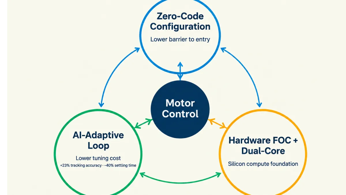
Trend 1: Zero-Code Control — Production Development Goes from "Writing Code" to "Setting Parameters"
Graphical configuration is replacing hand-written control loops. In 2026, zero-code toolchains for motor control enter mass production: current loops, speed loops, commutation timing, and protection thresholds are configured graphically, and driver code is generated automatically — sharply shortening the path from prototype to production. The implications for driver ICs are clear:
- Parameter accessibility: dead time, microstepping, current decay, and PWM frequency should all be exposed through register interfaces;
- Configuration as code: a companion host-side configuration tool lets FAEs and customers tune on site;
- Datasheet mapping: zero-code does not mean no datasheet — it means datasheet parameters map one-to-one onto configuration items.
Trend 2: AI Neural Networks in the Loop — Adaptive Speed Tracking and Disturbance Rejection
AI covers what classical PI/PID cannot. Neural networks applied to speed and position loops provide adaptive compensation for load steps, inertia variation, and parameter drift, with quantified gains: +23% speed-tracking accuracy and -40% settling time (Lumsyn public test data). Landing this on silicon takes three things: high-fidelity current and speed sensing data, a lightweight network that runs in real time on embedded cores (fixed-point or lookup-table based), and compute headroom that does not steal cycles from the control loop. For selection, this raises the weight of an IC's "data observability" — FG tachometer feedback, current-sense accuracy, and dead-time consistency are the foundation an AI loop can trust.
Trend 3: Hardware FOC Accelerator + Dual-Core — Moving the Loop into the Chip
One core runs real-time control; the other runs protocols and intelligence. Motor control chips are beginning to integrate hardware FOC accelerators with dual-core architectures: one core runs the real-time control loop (FOC or commutation), while the other handles host communication, protocol stacks, protection, and self-learning algorithms — divided cleanly, with no contention. The companion trend is higher integration: Hall and encoder interfaces, current-sense amplifiers, gate drive, and protection logic move into a single IC, cutting external component count.
The Roadmap: From "Power Stage" to "Control Stage"
Evolution is not a teardown — it stacks compute and usability layer by layer. First make everything configurable (zero-code), then make the loop adaptive (AI), and finally harden the compute into silicon (hardware FOC / dual-core):
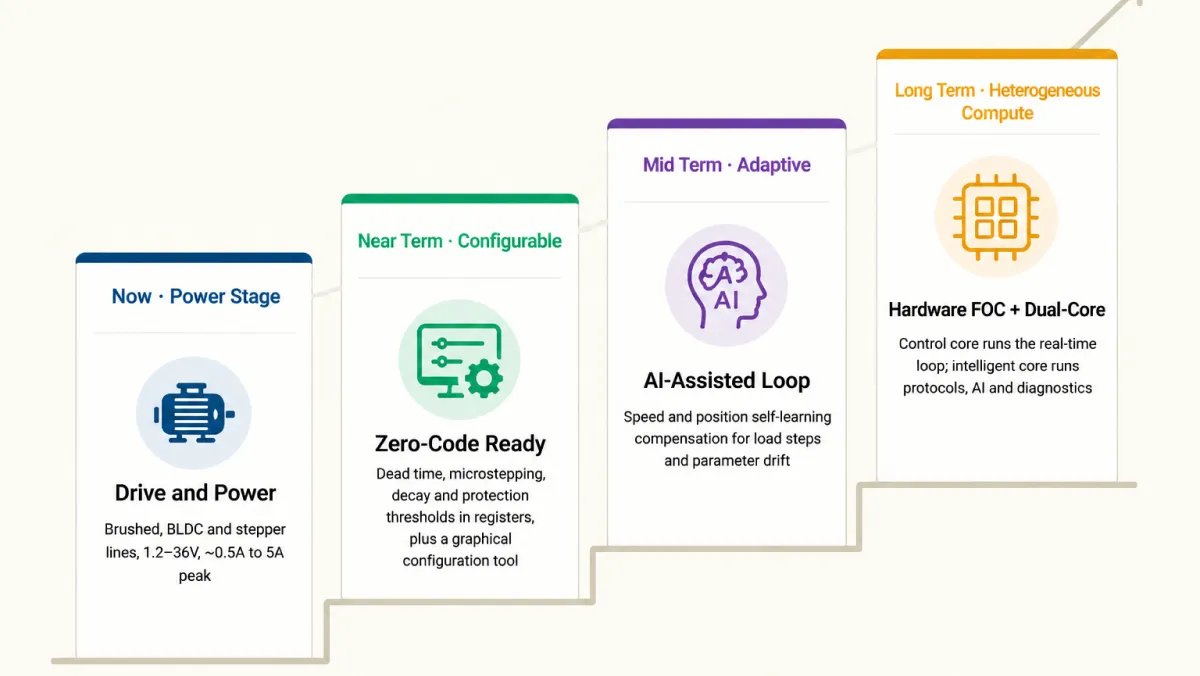
| Stage | Theme | What It Means |
|---|---|---|
| Now · Power stage | Drive and power | Three product lines covering 1.2–36V and roughly 0.5A to 5A peak, in integrated-driver and pre-driver forms |
| Near term · Configurable | Zero-code ready | Dead time, microstepping, decay, and protection thresholds fully register-based, with a graphical configuration tool for code-free field tuning |
| Mid term · Adaptive | AI-assisted loops | Self-learning speed and position compensation layered onto microstepping and FOC, handling load steps and parameter drift |
| Long term · Heterogeneous compute | Hardware FOC + dual-core | A control core runs the real-time loop while an intelligent core runs protocols, AI, and diagnostics — a complete motor control subsystem on one chip |
Three Product Lines, Three Next Stops
Brushed DC Drivers: Max Out Configurability, Embrace Zero-Code
Simple low-voltage drivers should harvest the zero-code dividend first. ST3901 is a low-voltage, micro-power single-channel driver (1.2–6V / 1.2A / 420mΩ, PWM-IN, thermal protection) for single-cell handheld devices; ST3909, ST8548, and ST8549 are dual-channel full bridges (3.8–12V / 1.5A per channel, 2.5A peak / 350mΩ) with built-in LDOs, differing in control logic (ST3909 and ST8548 use PWM IN/IN; ST8549 uses PWM IN/EN). Next stop: unify the IN/EN and speed-control configuration interface, move stall and overcurrent thresholds into registers, and deliver a "power-on-and-go" zero-code brushed solution.
BLDC Drivers: From "Commutation" to "Adaptive FOC"
The brushless line is the best landing zone for AI adaptivity and hardware FOC. The current lineup covers three forms: ST1262 and ST1298 are single-phase full-wave drivers with integrated power stages (3–20V / 1.55A, ST1262 peaks at 1.65A, with FG tachometer feedback) — the mainstay for fans and pumps; ST1267R is a single-phase full-wave pre-driver requiring external MOSFETs (5.5–16V), aimed at high-airflow, high-current server fans; ST4931P and ST4939 are three-phase 120° trapezoidal pre-drivers (4.7–36V / 7.5–36V, with Hall inputs, synchronous rectification, fixed 1µs dead time, UVLO/OVP); ST5958 is a three-phase sensorless sinusoidal driver with integrated FETs (1.8–6V / 500mA per phase, BEMF sensing, low noise and vibration). Next stop: add zero-code commutation configuration on top of ST5958 and the ST493x pre-drivers, then evolve toward adaptive speed loops and hardware FOC — exactly where the AI +23% / -40% gains are easiest to cash in.
Stepper Drivers: Microstepping + Self-Learning, Toward Silent Precision
Steppers already have the "high microstepping + digital interface" foundation. ST6208 is a camera lens driver (LGA44 6×6, PID-driven iris DC motor plus zoom/focus dual steppers, 256 microsteps, with Hall signal amplification); ST6209 is a dual-channel 5V low-voltage stepper driver (0.8A per channel / 256 microsteps, SPI, QFN44 5×5) for precision systems like camera zoom and gimbals — note the two serve different purposes and must not be interchanged. ST6609 is a standard two-phase stepper driver (4.7–36V / 2A, 4A peak, STEP/DIR + MS pin microstepping, AGC automatic torque compensation, standstill power saving, 100ns dead time); ST6610 is its upgraded sibling (4.2–36V / 2.5A, 5A peak) adding a one-wire UART interface and register configurability — already moving toward zero-code. Next stop: turn AGC torque compensation, standstill saving, and microstepping into one-click self-learning, add stall detection, and make steppers quieter and steadier in 3D printers, robots, and medical equipment.
One Table: STST Motor Driver Lineup at a Glance
Fourteen representative parts across the brushed, BLDC, and stepper lines. Parameters are taken from official datasheets; "—" marks items not specified:
| Part Number | Motor Type | Supply Voltage | Output Current | Rds(on) | Architecture / Algorithm | Interface | Package | Positioning / Evolution |
|---|---|---|---|---|---|---|---|---|
| ST3901 | Brushed | 1.2–6V | 1.2A | 420mΩ | H-bridge · PWM | PWM-IN | DFN10(3×3) | Zero-code ready |
| ST3909 | Brushed / full bridge | 3.8–12V | 1.5A/ch (2.5A peak) | 350mΩ | Dual full bridge · PWM | PWM(IN/IN) | SSOP10L | Zero-code ready |
| ST8548 | Brushed / full bridge | 3.8–12V | 1.5A/ch (2.5A peak) | 350mΩ | Dual full bridge · PWM | PWM(IN/IN) | SSOP10L | Built-in LDO |
| ST8549 | Brushed / full bridge | 3.8–12V | 1.5A/ch (2.5A peak) | 350mΩ | Dual full bridge · PWM | PWM(IN/EN) | SSOP10L | Built-in LDO |
| ST1262 | BLDC single-phase | 3–20V | 1.55A (1.65A peak) | 0.4–0.5Ω | Full-wave · integrated | PWM + FG | eTSSOP16L | FG feedback |
| ST1298 | BLDC single-phase | 3–20V | 1.55A | 0.4–0.5Ω | Full-wave · integrated | PWM + FG | TSSOP14-EP | FG feedback |
| ST1267R | BLDC single-phase | 5.5–16V | Pre-driver | — | Full-wave · pre-driver | External PWM | SSOP16 | External MOSFETs |
| ST4931P | BLDC three-phase | 4.7–36V | Pre-driver | — | 120° trapezoid · Hall | PWM + Hall | QFN28(5×5) | Pre-driver · SR |
| ST4939 | BLDC three-phase | 7.5–36V | Pre-driver | — | 120° trapezoid · Hall · SR | PWM + Hall | QFN28(5×5) | Pre-driver · SR |
| ST5958 | BLDC three-phase | 1.8–6V | 500mA/phase | Integrated FETs | Sinusoidal · sensorless BEMF | PWM | DFN3×3-10 | Sensorless sine |
| ST6208 | Lens driver | Low voltage | STM 0.8A / Iris DC 0.3A | — | PID iris · 256-microstep STM | SPI | LGA44(6×6) | Lens · Hall amplifier |
| ST6209 | Stepper | 5V | 0.8A/ch | — | Dual-channel STM · 256 microsteps | SPI | QFN44(5×5) | Low voltage · quiet |
| ST6609 | Stepper | 4.7–36V | 2A (4A peak) | — | Two-phase · 256 microsteps | STEP/DIR + MS | QFN28 | AGC · standstill saving |
| ST6610 | Stepper | 4.2–36V | 2.5A (5A peak) | — | Two-phase · 256 microsteps | STEP/DIR + UART | TSSOP28 | UART configurable |
Two Things to Keep in Mind
"Parameter Accessibility" Is the Foundation of Zero-Code
- Moving dead time, microstepping, decay, and protection thresholds into registers means one command changes them on site — no board respin;
- Graphical configuration turns "datasheet parameters" into "dropdown options," keeping FAEs and customers on the same page;
- The richer the configuration interface, the better one board serves wide-voltage, multi-load applications.
AI Loops Need Clean Data
- Current-sense accuracy, dead-time consistency, and FG feedback resolution determine how trustworthy the AI model's inputs are;
- Microstepping and sinusoidal modulation must be done right first, or self-learning has no stable baseline;
- Only fixed-point or lookup-table lightweight AI can run in real time on embedded cores.
Conclusion: STST's Three-Step Motor Driver Path
In 2026, motor drive competition shifts from "power specs" to "development usability + algorithm adaptivity + compute architecture." STST's path is clear: step one, fully register-map the brushed and stepper lines with graphical tools to harvest the zero-code dividend; step two, layer self-learning compensation onto BLDC and stepper microstepping and FOC to land AI gains in real products; step three, evolve from pre-driver and integrated-FET power stages toward a "control core + intelligent core" heterogeneous architecture, delivering a complete motor control subsystem on a single chip.
Next steps:
- Download datasheets: full electrical parameters, register maps, and package information for every part.
- Request free samples: submit part numbers and quantities online to start evaluation quickly.
- Contact the engineering team: one-on-one support for selection, substitution review, and configuration tuning.
FAQ
Will zero-code control replace hand-written FOC?
No — it layers rather than replaces. Standard mass-production scenarios (fans, pumps, appliance BLDC, general steppers) can be delivered quickly with zero-code configuration, while performance-limit designs, special topologies, and heavy customization still need low-level tuning by engineers. The value of zero-code is cutting 80% of standard production work from weeks to days, freeing engineers for the 20% of high-value problems.
How do the AI gains of +23% tracking accuracy and -40% settling time land on a driver IC?
Landing these gains on silicon takes three things. First, high-fidelity current and speed sensing data; second, a lightweight network that runs in real time on embedded cores (fixed-point or lookup-table based); third, a dual-core architecture where the intelligent core has the compute to run the model without starving the control core. The figures come from public motor-control research (Lumsyn test data, cited via Electrosens), using neural networks for adaptive compensation in speed and position loops against load steps, inertia variation, and parameter drift — exactly the value of evolving toward hardware FOC + dual-core.
How does a hardware FOC accelerator differ from a traditional pre-driver + MCU approach?
The traditional approach runs FOC in software on an external MCU; a hardware accelerator hardens the loop into dedicated logic. Software FOC consumes MCU frequency, with latency and power limited by software; a hardware FOC accelerator fixes the current loop and coordinate transforms into dedicated logic for better determinism and lower latency, and pairing it with a general-purpose core for protocols, protection, and self-learning gives the dual-core heterogeneous architecture. Existing ST493x pre-drivers and the ST1262 / ST5958 integrated solutions can serve as the power and sensing foundation of this architecture.
Which STST parts are already configurable, and which are still moving toward zero-code?
Already digital-interface or pin configurable: steppers ST6610 (UART), ST6208 / ST6209 (SPI, 256 microsteps), and ST6609 (MS pin microstepping + AGC). Primarily analog/PWM configured: BLDC ST4931P / ST4939 (PWM + Hall, fixed dead time), ST5958 (sensorless sine), and ST1262 / ST1298 (PWM / RC). Moving toward a unified graphical toolchain: brushed ST3901 / ST3909 / ST8548 / ST8549, plus the three-phase series extending toward hardware FOC + adaptivity.
Can ST6208 and ST6209 be used interchangeably?
No — they serve different purposes. ST6208 is a camera lens driver IC (LGA44 6×6) integrating a PID-driven iris DC motor channel and zoom/focus dual stepper channels with Hall signal amplification; ST6209 is a general-purpose dual-channel 5V low-voltage stepper driver (0.8A per channel, 256 microsteps, SPI, QFN44 5×5) for precision systems such as camera zoom and gimbals. Select based on whether you need an all-in-one lens driver or a general dual stepper.
Facing the zero-code and AI trends, which metrics should selection prioritize now?
Prioritize three metric groups: first, configuration-interface completeness (whether dead time, microstepping, decay, and protection thresholds are register-based), which determines how fast a zero-code toolchain gets you running; second, data observability (FG feedback, current-sense accuracy, dead-time consistency), which determines how trustworthy an AI loop can be; third, architectural headroom (pre-driver vs integrated FET, and whether a control-core / intelligent-core upgrade path exists), which determines how far the platform can go.