

AC-DC Power IC Selection: PSR, PWM & Non-Isolated from 5W to 40W
The Landscape: A "Price Hike + Domestic Substitution" Window in 2026
A stable lead time is itself a competitive edge. In the second half of 2026, TI, MPS, and Richtek raised power management IC prices collectively, and lead times of around 40 weeks are pushing computing, energy storage, and industrial OEMs to accelerate domestic substitution. For selection engineers: domestic supply chains are more trustworthy, design-in willingness is stronger, and supply stability is now a hard requirement.
AC-DC is the "energy heart" of chargers, adapters, appliances, set-top boxes, LED drivers, and power tools — pricing, lead time, and BOM simplicity directly determine a power supply’s cost structure and supply stability. The STST AC-DC family offers 16 part numbers plus 2 companion adjustable references across 5 routes (primary-side PWM / PSR / non-isolated / synchronous rectifier / CV-CC), with standby down to <30 mW and power up to 40 W.
The Power × Topology Map
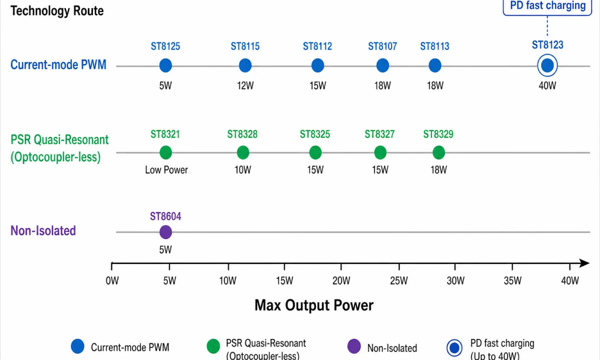
AC-DC selection starts with two questions: isolated or not, and how much power. The 16 parts span three topology routes; parts at the same power point have similar parameters — differentiate by package, startup current, and protection tiers:
| Topology | Typical P/N | Power Coverage | Standby Power | Positioning |
|---|---|---|---|---|
| Current-mode PWM (optocoupler feedback) | ST8125 / ST8115 / ST8112 / ST8107 / ST8113 / ST8123 | 5–40 W | <100 mW ~ <0.1 W | Mature loop, intuitive debugging; general-adapter mainstay |
| PSR quasi-resonant (optocoupler-less) | ST8321 / ST8325 / ST8327 / ST8328 / ST8329 | Low power ~ 18 W | <30 mW ~ <60 mW | No optocoupler or TL431; leaner BOM, higher reliability |
| Non-isolated regulation | ST8604 | 5 W | <100 mW (no load) | No transformer or optocoupler; budget choice for small appliances |
Scenario-Based Selection: Six Groups
Scenario 1: Low-Power Appliances — Standby Savings, Level-VI Efficiency
Conclusion: pick PSR for extreme low standby, conventional PWM for supply stability. Standby power is the first metric checked when set-top boxes, small appliances, and smart sockets upgrade efficiency grades.
- ST8125: 5 W universal / 6 W peak; integrated 700 V HV switch; standby <0.1 W, meets Energy Star 2.0.
- ST8115: 12 W universal / 18 W peak; built-in HV startup current source; adaptive frequency foldback lowers EMI.
- ST8328: PSR quasi-resonant 10 W; HV startup eliminates startup resistors; standby <30 mW — the family’s lowest.
Scenario 2: General-Purpose Adapters — Current-Mode PWM, Delivery Mainstay
Conclusion: ST8112 for the mainstream 15 W tier, ST8107 for voltage margin, ST8113 for peak headroom. 15–24 W general adapters emphasize EMI friendliness, full protection, and stable supply.
- ST8107: 18 W flyback; optional 600/650/700 V integrated MOS; 65 kHz with frequency dithering; burst mode standby <100 mW.
- ST8112: 15 W max / 18 W peak (85–265 V universal); 650 V/2 A MOS; only 10 µA startup current.
- ST8113: 18 W max / 24 W peak; 600 V/4 A MOS, RDS(on) ≤3.3 Ω; light-load green mode, no audible noise.
Scenario 3: Optocoupler-Less PSR — BOM Cost-Down
Conclusion: for cost-down plus reliability, PSR offers the best value today. Primary-side regulation removes the optocoupler, TL431, and compensation network, cutting cost and area at the source.
- ST8321: PSR CV/CC for low power; suits chargers and LED drivers; quasi-resonant valley switching, high efficiency and low EMI.
- ST8325 / ST8327: 15 W max, 650 V/2 A MOS; Level-VI efficiency; the ST8327 also comes in a COOLMOS version (2.2 Ω).
- ST8329: 18 W max, 650 V/4 A MOS; cable drop compensation; DIP7 / SOP7 options.
Scenario 4: Mid-to-High Power — PD Fast Charging
Conclusion: the ST8123 is the first choice for fast charging; add synchronous rectification for efficiency. 36–40 W PD chargers must balance low standby, low startup current, and overpower compensation.
- ST8123: 36 W max, 40 W with heatsinking; 650 V/7 A MOS, RDS(on) ≤1.4 Ω; startup current as low as 5 µA; standby <100 mW.
Scenario 5: Non-Isolated — Budget Power for Small Appliances
Conclusion: once the system permits non-isolated design, the ST8604 is the component-saving choice. No transformer or optocoupler — the simplest periphery at the lowest cost, for control-board power in small and white goods.
- ST8604: 5 W max non-isolated regulation; boost / buck-boost / flyback topologies; integrated 650 V MOS plus HV startup; power-save mode keeps light-load efficiency high.
Scenario 6: Efficiency Companions — Synchronous Rectifiers, CV/CC, References
Conclusion: efficiency, closed loop, and reference each have a dedicated part. Synchronous rectifiers cut secondary-side rectification loss; CV/CC controllers and adjustable references build precise constant-voltage/constant-current loops.
- ST8411 / ST8415: synchronous rectifier controllers. ST8411 supports 3–6 V (DCM/QR) with 50 ns turn-off delay; ST8415 supports 5–20 V (DCM/CCM/QR) with only 22 ns delay.
- ST4312 / ST4315: CV/CC controllers with a 1.21 V reference; ST4312 runs VCC 3–40 V at up to ±0.5% accuracy; ST4315 draws only 0.85 mA quiescent.
- ST431 / ST432: adjustable precision references (2.5 V/0.4% and 1.25 V/0.5%) for feedback loops and reference setting.
Master Table: 16 Parts Side by Side
| P/N | Circuit Type | Vin Range | Typical Power | Key Advantages / Protection | Package |
|---|---|---|---|---|---|
| ST8107 | Current-mode PWM flyback 65 kHz | Universal (—) | 18 W | Optional integrated 600/650/700 V MOS; frequency dithering; burst-mode standby <100 mW | DIP8 |
| ST8112 | Current-mode PWM 67.5 kHz | 85–265 V universal | 15 W / 18 W peak | 650 V/2 A MOS; 10 µA startup current; dithering + green mode + five protections | DIP7 |
| ST8113 | Current-mode PWM 70 kHz | Universal (—) | 18 W / 24 W peak | 600 V/4 A MOS, RDS(on) ≤3.3 Ω; green mode, no audible noise | DIP7 |
| ST8115 | Current-mode PWM 60 kHz | Universal (—) | 12 W / 18 W | 700 V bipolar integrated switch; HV startup; standby <0.1 W; frequency foldback lowers EMI | DIP8/7 |
| ST8123 | Current-mode PWM 67.5 kHz | Universal (—) | 36 W / 40 W with heatsink | 650 V/7 A MOS, RDS(on) ≤1.4 Ω; 5 µA startup; PD fast-charging positioning | DIP8 |
| ST8125 | Current-mode PWM 60 kHz | Universal (—) | 5 W / 6 W peak | 700 V bipolar integrated switch; standby <0.1 W; line compensation + LPS control | SOP6 |
| ST8321 | PSR quasi-resonant ≤120 kHz, CV/CC | — | Low power (LED/charging) | Optocoupler-less, no TL431; valley switching, low EMI; standby <60 mW | SOP7 |
| ST8325 | PSR quasi-resonant | — | 15 W | Optocoupler-less; 650 V/2 A MOS; Level-VI efficiency; standby <60 mW | DIP7 |
| ST8327 | PSR quasi-resonant | — | 15 W | 650 V/2 A COOLMOS (2.2 Ω); standby <60 mW | SOP7 |
| ST8328 | PSR quasi-resonant + HV startup | — | 10 W | Standby <30 mW — family lowest; no startup resistors | SOP7 |
| ST8329 | PSR quasi-resonant | — | 18 W | 650 V/4 A MOS; cable drop compensation; standby <60 mW | DIP7/SOP7 |
| ST8604 | Non-isolated boost/buck-boost/flyback | — | 5 W | Integrated 650 V MOS + HV startup; power-save mode; no-load <100 mW | SOP7 |
| ST8411 | Synchronous rectifier, DCM/QR | 3–6 V output side | — | 50 ns turn-off delay; cuts body-diode loss | SOP8 |
| ST8415 | Synchronous rectifier, DCM/CCM/QR | 5–20 V output side | — | Only 22 ns turn-off delay; wider coverage | SOT23-5 |
| ST4312 | CV/CC controller | VCC 3–40 V | — | 1.21 V reference; ±1% (A/B) or ±0.5% (C) accuracy | SOP8 |
| ST4315 | CV/CC controller | VCC 3–36 V | — | 1.21 V reference; ±1% accuracy; only 0.85 mA quiescent | SOT23-6 |
Companion adjustable references: ST431 (2.5 V / 0.4%, TO-92, SOT23-3) and ST432 (1.25 V / 0.5%, SOT23-3, TO-92). "—" marks items not specified in the source materials; always refer to the latest official datasheets.
Two Key Insights
What Removing the Optocoupler Actually Saves
- Leaner BOM: no PC817/EL817 optocoupler, TL431 reference, or compensation network.
- Higher reliability: one less isolated transfer stage, avoiding optocoupler CTR aging drift.
- Minimal footprint: enables single-sided boards and high-density layouts.
What the 30 / 60 / 100 mW Standby Tiers Mean
- <30 mW (ST8328): the strictest Level-VI efficiency and always-on devices.
- <60 mW (ST832x PSR family): mainstream charger/adapter efficiency.
- <100 mW (ST81xx): general small-appliance standby requirements.
Three Steps to Lock In Your STST AC-DC
- Step 1: isolated or not. Chargers, adapters, and appliance mains needing safety isolation → ST81xx / ST832x; low-power control boards allowing non-isolated design → ST8604.
- Step 2: power and efficiency positioning. Map output power to the right tier; for strict standby go straight to the ST8328 (<30 mW) or the low-standby PSR family.
- Step 3: cost-down and efficiency companions. Leaner BOM → optocoupler-less PSR; higher efficiency → add synchronous rectification; CV/CC or feedback → CV/CC controllers plus adjustable references.
Choosing AC-DC amid price hikes means choosing the combination of stable supply, low standby, simple periphery, and certified efficiency. STST’s 16 part numbers plus 2 companion references line up the whole path from 5 W to 40 W. Parameters are subject to official datasheets; final selection should be evaluated against system-level safety and efficiency certification.
Next steps:
- Download Datasheet: get full electrical parameters and package information for each part number.
- Request Free Samples: submit part numbers and quantities online to start evaluation.
- Contact Engineering Team: one-on-one selection and replacement support from our FAE team.
FAQ
What is the practical impact of the current price increases on AC-DC selection?
Overseas majors (TI, MPS, Richtek, etc.) raised prices collectively in June–July 2026 with extended lead times. Selection should now weigh three things more heavily: whether domestic substitution is needed to lock lead time and supply; whether the IC itself saves periphery (optocoupler-less design, integrated power switch, HV startup) to offset price increases at the BOM level; and whether it meets efficiency standards to avoid rework. STST integrates the power switch across the family, and some parts add optocoupler-less PSR plus HV startup — covering all three points.
How do I choose between optocoupler feedback (current-mode PWM) and primary-side regulation (PSR)?
Optocoupler feedback (ST8107/8112/8113, etc.) uses mature loops with intuitive debugging, suiting general adapters that demand high accuracy and EMI performance and can accept slightly more periphery. PSR (ST832x family) removes the optocoupler and TL431 — leaner BOM, higher reliability, Level-VI efficiency — and is the mainstream direction for cost-down and reliability. Prefer PSR for low cost plus high reliability; choose current-mode PWM when you need more complex feedback or point-to-point control. For higher power (36 W+), consider the ST8123 current-mode PWM with synchronous rectification for efficiency.
How low can STST AC-DC standby power go? Can it meet Level-VI efficiency?
Yes. The lowest is the ST8328 at under 30 mW standby with HV startup; the ST832x PSR family stays under 60 mW; the conventional ST81xx PWM family stays under 0.1 W (100 mW). Level-VI efficiency mainly constrains standby and average efficiency at low power, so the 30–60 mW tiers are comfortable — combined with low startup current and green mode, mainstream certification is achievable.
How do I decide between non-isolated (ST8604) and isolated AC-DC designs?
Isolated AC-DC (ST81xx/ST832x) uses a transformer for safety isolation, suiting chargers, adapters, and appliance mains supplies that must pass safety regulations with isolated input/output. The non-isolated ST8604 removes the transformer and optocoupler for the simplest periphery and lowest cost, but provides no isolation — it only fits low-power control-board supplies where the system permits non-isolated design (auxiliary power in some small and white goods). Safety-first designs must be isolated; cost/area-first designs that allow non-isolated operation can use the ST8604.
Which primary controller should the synchronous rectifiers (ST8411/ST8415) pair with?
The ST8411 suits 3–6 V outputs on primary-side flyback stages operating in DCM/QR; the ST8415 supports 5–20 V across DCM/CCM/QR for wider coverage. Both sit at the secondary-side rectification position, replacing conventional rectifier diodes and using short turn-off delay (only 22 ns on the ST8415) to cut body-diode conduction loss and raise efficiency. They pair with mid-to-high-power PWM controllers like the ST8123 or with PSR flybacks — choose the ST8411 or ST8415 according to the system’s output rail.
How can I quickly narrow down STST part numbers by power level?
① Under 5 W where non-isolated is acceptable → ST8604; ② up to 12 W small appliances / strict standby → ST8125 / ST8115 / ST8328; ③ 10–18 W adapters / LED → ST832x (PSR optocoupler-less) or ST8115; ④ 15–24 W general adapters → ST8112 / ST8107 / ST8113; ⑤ 24–36 W → derate the ST8123 (36 W max); ⑥ 36–40 W fast charging / high power → ST8123 with heatsinking. For more efficiency add ST8411/15 synchronous rectifiers; for CV/CC charging or LED add ST4312/15; for feedback references use ST431/432.