

STST 1200V SiC MOSFETs: Military-Grade Reliability Meets New-Energy Efficiency
Why SiC Now: From "Costly Option" to "Default Choice"
The second half of the SiC story is underway, and the question has shifted from "whether to use it" to "how to select and deploy it." The global SiC power semiconductor market crossed USD 4 billion for the first time in 2025 and is projected to pass USD 10 billion by 2030, according to public data from Hangjia Shuo Research and Yole. Demand is not driven by a single sector: electric vehicles, PV-plus-storage, and charging infrastructure all remain strong, while high-voltage power delivery for AI data centers (AIDC) is approaching an inflection point. SiC is moving from a premium option to a default component in power systems.
The cost inflection has already arrived. Substrate manufacturing accounts for roughly 47% of total SiC device cost, and epitaxy for about 23% — together around 70%, per a 2026 Shanghai Securities News industry survey, with some variation across years and capacity phases. As 8-inch wafer technology matures and capacity ramps, substrate costs have dropped sharply, bringing SiC device pricing into a range downstream designers can accept. For engineers, the focus shifts accordingly: how SiC guarantees reliability in military-grade equipment, how it squeezes efficiency in new-quality-productivity scenarios, and how to select the right part for a specific board. Those are the three questions this article answers.
Material Physics: Why SiC Is Both Rugged and Efficient
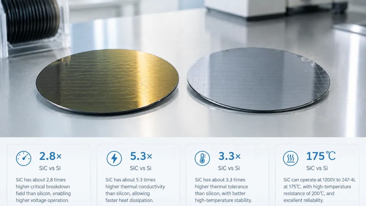
Every system-level benefit traces back to intrinsic material parameters. Compared with silicon, silicon carbide holds a generational lead on three key metrics (per public data from EET-China):
| Material Parameter | SiC vs. Si | Engineering Meaning |
|---|---|---|
| Bandgap | ~2.8× | More headroom under high voltage; lower leakage at high temperature |
| Critical field strength | ~5.3× | Thinner drift layer at the same voltage rating; lower on-resistance |
| Thermal conductivity | ~3.3× | Heat exits faster; more stable operation in hot environments |
| Rated junction temperature | 175°C (mainstream for 1200V TO-247-4L parts) | 200°C belongs to extended high-reliability grades |
- Switching losses drop sharply: SiC MOSFETs have no current tailing; the body diode's reverse recovery charge is only about 5% of a silicon counterpart. An external SiC Schottky diode (SBD) shows almost no reverse recovery tail at all, with recovery times down to 20ns or less, enabling switching frequencies around 200kHz and much higher system power density.
- Stability in hot environments: in sealed, high-voltage, poorly cooled conditions, SiC's temperature tolerance and thermal conductivity directly shrink the heatsinking hardware — a hard requirement for equipment power supplies.
- A natural fit for high-frequency, high-density designs: at voltage classes that demand high switching frequency, high power density, and high efficiency, SiC clearly outperforms conventional silicon IGBTs. IGBTs still hold their ground in very-high-current, cost-sensitive, low-frequency legacy applications — the two are not a simple substitution.
Note: the multipliers above are industry-published intrinsic material figures. Sources differ slightly (some cite ~10× for critical field strength); this article uses one consistent set of values purely to illustrate SiC's generational advantage over silicon.
Military Scenarios: Welding Reliability into Every Watt
Military qualification does not reward impressive peak specs; it rewards long-term, stable, failure-predictable operation under harsh conditions. SiC satisfies high reliability, high power density, and environmental ruggedness at the same time, which is why its standing in defense and aerospace power design is rising fast (per Electropages coverage of military electrification).
One published engineering case illustrates the trend: an all-SiC radar array power supply prototype reached 94.5% efficiency and 6W/cm³ power density under high-voltage input and low-voltage high-current output, roughly halving volume versus conventional supplies while withstanding pulsed loads and extended operation (per EET-China). These figures come from a public industry prototype, not from STST measurements. They show that SiC is becoming the backbone of miniaturized, high-efficiency, high-reliability power equipment; actual device selection must be evaluated independently against datasheet parameters and target operating conditions.
Demand Profiles at Three Application Levels
To avoid sensitive details, we discuss application levels and demand characteristics only — no specific equipment or system parameters:
| Application Level | Demand Profile | What SiC Delivers | Selection Focus |
|---|---|---|---|
| Radar / sensing array power | Sealed high-heat environment, high-voltage input, low-voltage high-current output, high power density | Better high-temperature tolerance with slimmer cooling; higher frequency shrinks magnetics; higher efficiency supports stronger transmit power | Input voltage rating, high-temperature RDS(on) behavior, package thermal capability, lot-to-lot consistency with traceability |
| Shipboard / vehicle integrated power | High-power conversion, bidirectional energy flow, shock and vibration, power-domain isolation | Higher-efficiency bidirectional AC/DC and DC/DC conversion; less weight and volume per watt; fast switching reduces cooling demand | Continuous and transient current capability, peak margin, junction temperature rating, mechanical and thermal reliability across wide temperature and vibration |
| Aerospace / special power supplies | Wide temperature range, high reliability, long service life, sovereign supply chain | Stable power over long cycles; a maturing, traceable domestic materials and device chain; generous high-temperature margin | Supply-chain traceability, lot consistency, sample burn-in verification, and failure-analysis support |
A Necessary Reality Check: Material Advantage ≠ Equipment-Ready
SiC's temperature tolerance and thermal conductivity do not mean a discrete device can be bolted straight into a radar or a ship. High-reliability requirements for military and special equipment come down to two pieces of "invisible engineering":
- Gate oxide reliability: the gate oxide is one of SiC's long-term weak points. Review gate-oxide aging, gate-bias stress, and HTGB (high-temperature gate bias) qualification data. Fast switching and narrow gate-voltage margins mean gate drive and protection design cannot be an afterthought.
- Lot traceability and DPA: military programs impose hard requirements on lot consistency and source traceability, typically involving destructive physical analysis (DPA), lot sampling, and screening. Confirm at selection time whether the vendor can provide lot reports, failure analysis, and a traceability chain.
Performance is the entry ticket; reliability is the moat. SiC wins in equipment power by satisfying the hard constraints together: high-temperature stability under high voltage, small volume at high power, and traceability over long service cycles.
New-Quality-Productivity Scenarios: Squeezing Efficiency out of Every Kilowatt-Hour
New quality productivity means technology-driven efficiency gains and lower energy consumption — and SiC sits right on the "energy highway" of power electronics. Peak traction-inverter efficiency above 99% (silicon designs typically sit at 94–98%), 8–15% more range from the same battery, 800V platforms pushing fast-charging power into the hundreds of kilowatts, and electric control units roughly halved in size and weight — these are shared requirements across new energy and compute-power synergies (per public reports from KePu China and Shanghai Securities News).
| Scenario | Where SiC Fits | System-Level Gains |
|---|---|---|
| Electric vehicles | Traction inverters, on-board chargers (OBC), DC-DC converters | 800V platforms plus SiC push peak inverter efficiency toward 99% and fast-charging power to hundreds of kW; SiC models accounted for about 58% of Chinese-brand EV sales in 2025 (per Hangjia Shuo Research) |
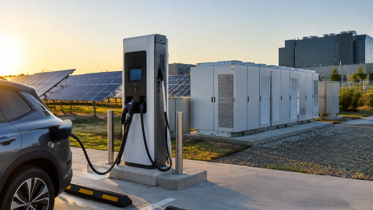
| PV, storage, and charging | PV inverters, power conversion systems (PCS), charging modules | Higher inverter efficiency, smaller footprint, longer service life, more energy yield per site; new national efficiency standards for chargers accelerate SiC adoption |
| AI data centers and compute-power synergy | 800V power architectures, solid-state transformers, compute power supplies, high-voltage DC links | AIDC high-voltage delivery drives continuous SiC growth across the 0.3–10kV range; the industry calls SiC the "power steward" of the AI era |
| High-end industrial and emerging fields | Industrial power supplies, high-frequency equipment, rail traction, eVTOL | SiC's wide temperature range and high-frequency capability carry it into more premium power applications |
The STST 1200V SiC Platform: Current Lineup
One platform, three tiers — selection becomes a single trade-off. STST's SiC portfolio focuses on a 1200V enhancement-mode planar MOSFET platform; the parts differ only in on-resistance and current class. Parameters below are transcribed from official STST datasheets:
| Part Number | VDS | ID (TC=25°C) | ID (TC=100°C) | RDS(on) typ | Package | Positioning |
|---|---|---|---|---|---|---|
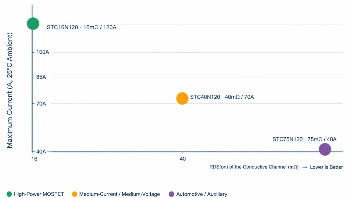
| STC16N120 | 1200V | 120A | 85A | 16mΩ | TO-247-4L | High current / ultra-low RDS(on); the workhorse for traction and high-power conversion |
| STC40N120 | 1200V | 70A | 50A | 40mΩ | TO-247-4L | Comfortable mid-current tier; balanced power density and cost |
| STC75N120 | 1200V | 40A | 30A | 75mΩ | TO-247-4L | Compact power modules / auxiliary supplies; datasheet marked AEC-Q101 Qualified |
Note: ID is the continuous current rating at case temperature (TC). The 25°C figure is the datasheet nominal, not a current the device sustains indefinitely on a heatsink — real designs must be derated against the 100°C figure, thermal design, junction temperature, and derating rules. Never select directly off the 25°C peak.
Match the Tier to the Job
High-Power Main Conversion: Current Is the Hard Metric — STC16N120
Push conduction loss to the platform floor first. In EV traction, high-power motor drives, shipboard and vehicle power conversion, and high-power industrial supplies, voltage drop and temperature directly determine cooling and reliability. The 16mΩ / 120A (25°C case) combination sets the loss floor of the platform.
Mid-Current Balance: Power and Cost Together — STC40N120
The balanced default. PV inverters, storage PCS, charging modules, and general industrial conversion need real current but not the extreme, while BOM cost and system efficiency still matter. The 40mΩ / 70A middle tier sits right on the sweet spot.
Automotive / Auxiliary Power: Reliability First — STC75N120
The AEC-Q101 qualification is a concrete advantage. Vehicle auxiliary drives, compact power modules, high-voltage auxiliary supplies, and airborne or vehicle power units impose hard requirements on reliability, automotive qualification, and supply-chain traceability — without extreme current demand. STC75N120's datasheet-marked AEC-Q101 Qualified status maps directly onto these cases.
Four Pitfalls to Avoid in Practice
- 1. Don't read only the 25°C ID — the hot rating is the real yardstick. The 100°C figure is much closer to actual operating conditions; high-voltage, high-current, long-duration operation must keep margin against the hot rating. Estimate junction temperature with TJ = TA + (Pcond+Psw) × RθJA and design the TO-247-4L thermal path properly.
- 2. Spend the high-frequency dividend wisely — gate drive and EMI still cost effort. SiC switches fast, and higher frequency shrinks magnetics, but the driver circuit, gate resistors, and loop layout must keep pace. Switching loss rises with frequency, so high frequency is not free; trade a little frequency for stability when needed.
- 3. "Automotive-grade" is not "military-grade" — read reliability qualifications in layers. AEC-Q101 targets vehicle environments; military and special applications usually demand stricter lot traceability, burn-in, and failure prediction. Define the target reliability level first, then match device qualification and supply-chain traceability to it.
- 4. Don't overlook packaging and system integration. The TO-247-4L Kelvin-source pin is friendlier to gate-drive timing and dead-time design, but its layout rules differ from three-pin parts. When paralleling devices, watch RDS(on) consistency, thermal coupling, and current sharing to avoid local hot spots.
Conclusion: Reliability and Efficiency on the Same Die
A SiC MOSFET looks like just one device in the power chain, yet it carries two core demands at once: the military's call for long-term reliability under harsh conditions, and new quality productivity's call for an efficiency leap in every kilowatt-hour. STST enters with a 1200V platform and three tiers at 16/40/75mΩ, covering high-power, balanced, and automotive-auxiliary scenarios — a practical, extensible path for domestic SiC. For engineers, the second half of SiC is not a yes-or-no question, but a combined one: which voltage, which resistance tier, and which reliability grade to design in. That is the problem STST wants to solve with you.
Next steps:
- Download datasheets: full electrical parameters and package information for STC16N120 / STC40N120 / STC75N120.
- Request free samples: submit part numbers and quantities online to start evaluation quickly.
- Contact the engineering team: one-on-one support for AEC-Q101 reports, lot traceability, and custom voltage tiers.
FAQ
How do I choose between a SiC MOSFET and a silicon IGBT?
SiC wins in high-frequency, high-density, high-efficiency designs; IGBTs still lead in very-high-current, cost-sensitive, low-frequency legacy applications. Above 1000V, where high switching frequency and power density matter (EV traction, PV plus storage, the grid), SiC holds clear advantages in switching loss, temperature tolerance, and power density. Silicon IGBTs remain strong where current is extreme, cost is paramount, and frequency is low. The two are not a simple substitution — evaluate voltage, frequency, efficiency, cooling, and cost together.
How should RDS(on) and current rating ID be matched in selection?
Lower RDS(on) cuts conduction loss and heat; higher ID supports more output power — and the two usually trade off. For high-power, loss-first cases (traction, high-power conversion), pick the low-resistance high-current tier STC16N120 (16mΩ / 120A). For moderate current with cost-efficiency balance, pick the middle tier STC40N120 (40mΩ / 70A). When reliability and automotive qualification come first and current demand is modest, pick STC75N120 (75mΩ / 40A).
Why do military applications value SiC so highly?
Military programs prize long-term reliability under harsh conditions — exactly SiC's strength. SiC's intrinsic temperature tolerance far exceeds silicon; mainstream 1200V TO-247-4L commercial parts are rated at a 175°C junction temperature, with far better high-temperature thermal handling than silicon solutions, staying stable in hot, high-power, poorly cooled enclosures. That said, every reliability claim must ultimately rest on gate-oxide qualification, lot traceability, burn-in screening, and failure analysis.
Is SiC still too expensive to use? Has the cost inflection arrived?
The cost inflection has arrived, and SiC is moving from a premium option to a default choice. Substrate (~47%) and epitaxy (~23%) together account for about 70% of SiC device cost (per a 2026 Shanghai Securities News survey, varying by year and capacity phase). As 8-inch wafer production ramps, substrate costs have dropped sharply and device pricing is now in an acceptable range for downstream designs. Whether it is "affordable" depends on system-level returns — higher efficiency and smaller volume often dilute total equipment cost.
Does AEC-Q101 qualification equal military-grade reliability?
No, they are not equivalent. AEC-Q101 is a reliability qualification for vehicle environments — the entry ticket for automotive applications. Military and special applications usually impose stricter requirements on lot traceability, destructive physical analysis (DPA), burn-in screening, and failure prediction. Define the target reliability level of your scenario first, then match device qualification and supply-chain traceability to it, rather than stretching one qualification to cover every demand.
What is the fourth pin of the TO-247-4L package for?
The fourth pin is a Kelvin source, which separates the driver loop from the power loop. It reduces the interference of source parasitic inductance on the gate drive, making switching faster, more stable, and lower-loss, and it is friendlier to gate-drive timing and dead-time design. Its layout rules differ from a standard three-pin TO-247, so treat it accordingly in PCB design.